Fundamentals for rapid prototyping
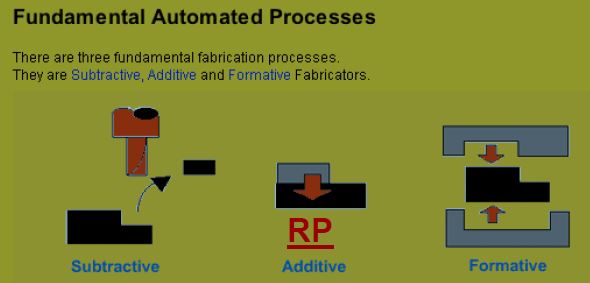
Regardless of the different techniques used in the RP systems developed, they adopt the same basic approach, which can be described as follows:
Regardless of the different techniques used in the RP systems developed, they adopt the same basic approach, which can be described as follows:
- A model or component is modeled on a computer-aided design - computer-aided manufacturing (CAD-CAM) system. the model which represents the physical part to be built must be represented as closed surfaces which unambiguously define an enclosed volume. This means that the data must specify the inside, the outside and the boundary of the model. This requirement will become redundant if the modeling techniques used is based on solid modeling. this is by virtue that a valid solid model will automatically have an enclosed volume. this requirement ensures that all horizontal cross-sections that are essential to RP are closed curves to create the solid object.
- The solid or surface model to be built is next converted into a format dubbed the "STL" (StereoLithography) file format which originates from 3D Systems. The STL file format approximates the surfaces of the model by polygons. Highly curved surfaces must employ many polygons, which mean that STL files for curved parts can be very large.
- A computer program analyzes an .STL file that defines the model to be fabricated and "slices" the model into cross-sections. The cross-sections are systematically recreated through the solidification of either liquids or powders and then combined to form a 3D model.
The basic process
1. CREATING THE 3D CAD MODEL OF THE DESIGN
2. CONVERTING THE CAD MODEL INTO STL FORMAT
3. SLICING THE STL FILE INTO THIN LAYERS
4. CONSTRUCTING THE MODEL ONE LAYER ATOP OF ANOTHER
5. CLEANING AND FINISHING THE MODEL
1. Creating the 3D CAD Model of the design
First the object to be build is modeled:
First the object to be build is modeled:
- using a CAD software package
- or by using a laser scanner or a Coordinate Measuring Machine (CMM). (”Reverse engineering””)
2. Converting the CAD model into STL format
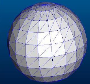
The standard data interface between CAD software and the machine is the STL-format (Stereolithography).
An STL-file approximates the shape of a part using triangular facets. Small facets produce a high quality surface.
The standard data interface between CAD software and the machine is the STL-format (Stereolithography).
An STL-file approximates the shape of a part using triangular facets. Small facets produce a high quality surface.
3. Slicing the STL file
Triangular Facets
|
|
4. Constructing the model
The fourth step is the actual construction of the part. Using one of several techniques (described in the 6 types) RP machines build the model layer by layer.
The material´s initial states are:
- LIQUID
- SOLID
- POWDER
5. Clean and Finish
- Removing of the part from the machine
- Detaching any supports
- Aftercure (some photosensitive materials)
- Cleaning and surface treatment
- Possible painting (other finishes)
