The term rapid prototyping (RP) refers to a class of technologies that can automatically construct physical models from Computer Aided Design (CAD) data. The main advantage of the system is that almost any shape can be produced. Time and money savings vary from
50 – 90% compared to conventional systems. Rapid prototyping techniques are often referred to solid free-form fabrication, computer automated manufacturing or layered manufacturing. The computer model is sliced into thin layers and the part is fabricated by adding layers on to of each other. Rapid prototyping process belong to the generative (or additive) production process unlike subtractive or forming processes like lathing, milling, grinding or coining, in which form is shaped by material removal or plastic deformation.
In all commercial RP processes, the part is fabricated by deposition of layers countered in a (x-y plane two dimensionally. the third dimension (z) results from single layers being stacked up on top of each other, but not as a continuous z-coordinate. This results in the prototypes being very exact in the x-y plane but have stair-stepping in the z-direction. Smaller z-stepping will result in the prototype looking more like the original. RP is classified into two fundamental process steps namely "generation of mathematical layer information and "generation of physical layer model.
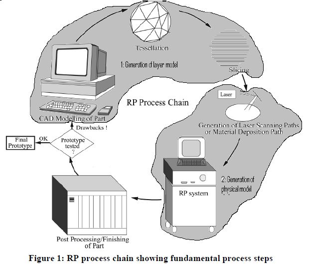
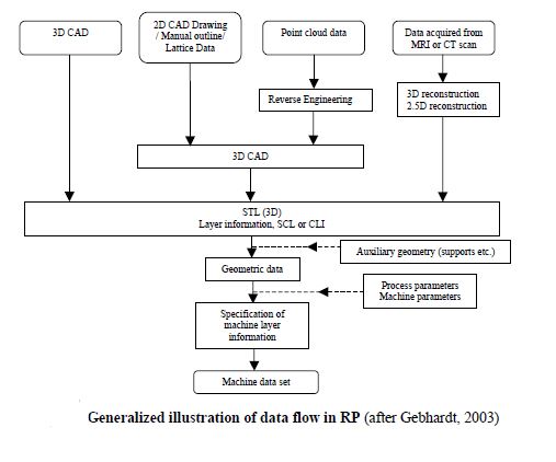
It can be seen from above that the process starts with 3D modelling of the product, then a STL file is exported by tessellating the geometric 3D model. In tessellation various surfaces of a CAD model are piecewise approximated by a series of triangles (figure 2) and co-ordinate of vertices of triangles and their surface normals are listed. The number and size of triangles are decided by facet deviation or chordal error as shown in figure 2. These STL files are checked for defects like flip triangles, missing facets, overlapping facets,
dangling edges or faces etc. and are repaired if found faulty. Defect free STL files are used as an input to various slicing softwares. At this stage choice of part deposition orientation is the most important factor as part building time, surface quality, amount of support structures, cost etc. are influenced. Once part deposition orientation is decided and slice thickness is selected, tessellated model is sliced and the generated data in standard data formats like SLC (stereolithography contour) or CLI (common layer interface) is stored. This information is used to move to step 2, i.e., generation of physical model. The software that operates RP systems generates laser-scanning paths (in processes like Stereolithography, Selective Laser Sintering etc.) or material deposition paths (in processes like Fused Deposition Modeling). This step is different for different processes and depends on the basic deposition principle used in RP machine. Information computed here is used to deposit the part layer-by-layer on RP system platform.
The final step in the process chain is the post-processing task. At this stage, generally some manual operations are necessary therefore skilled operator is required. In cleaning, excess elements adhered with the part or support structures are removed. Sometimes the surface of
the model is finished by sanding, polishing or painting for better surface finish or aesthetic appearance. Prototype is then tested or verified and suggested engineering changes are once again incorporated during the solid modeling stage.